Project 6
Project 6A: Mini-particle accelerator
Your team has been hired as part of a larger team that is developing a micro-particle accelerator. Your team is tasked with modelling the initial part of the accelerator, which uses a constant electric field to accelerate the charges. The concept is that the particles will enter a tube that is encapsulated by rings of charge. Your team needs to demonstrate that this concept will produce a constant electric field.
Part 1:
The first bit of code that you have received is from the previous team who were able to construct a single ring of charge and show the electric field due to that ring at some point. Your team should construct the electric field vectors for a circle inside the accelerator (smaller than the ring) at a distance of a few centimeters from the ring face.
R = 0.02
Q = 1e-9
N = 20

myring = ring(pos = vector(0,0,0), radius = R, axis = vector(0,0,1), color = color.blue, thickness = 0.02*R)

oofpez = 9e9 #1/(4pi epsilon_0) in N m^2/C^2
dq = Q/N #charge of a piece

Enet = vector(0,0,0) #net electric field of all pieces

scale=1e-5

ObsList = []

phi = 0
dphi = pi/4


point = sphere(pos = vector(0,0.01,0.05), color = color.red, radius = R/40)
rpoint = point.pos #location of the point in space to calculate E field

dtheta = 2*pi/N #theta increment for our loop
theta = dtheta/2 #initial theta for first piece of loop

while theta<2*pi:

    rpiece = R*vector(cos(theta),sin(theta),0) #location of piece
    r = rpoint - rpiece #vector from piece to point in space
    rmag = mag(r) #magnitude of r
    rhat = norm(r) #unit vector for r

    dE = oofpez*dq/rmag/rmag*rhat #Electric field due to piece at rpoint
    Enet = Enet + dE #net electric field of the first one up to this one

    particle = sphere(pos = rpiece, radius = 2*point.radius, color = color.yellow)

    theta = theta + dtheta

Evector = arrow(pos = rpoint, axis = scale*Enet, color = color.orange)
Part 2
After you got this initial code working, your team was able to construct a model of a tube consisting of multiple rings, all with the same charge. But, the field doesn't look quite right - it's not constant as expected. Your bosses seem to think the field can be made constant in the tube, so it's up to you to figure out how.
num_points = 10
num_rings = 11
N = 11
spacing = 0.02

# Set some constants and stuff
R=0.02 #radius of ring in m
ax = vector(0,0,1) # simplify things
Q=1e-9 #charge of ring in C
oofpez=9e9 #1/(4pi epsilon_0) in N m^2/C^2

#draw axis
zaxis=cylinder(pos=-2*R*ax, radius=0.015*R, axis=4*R*ax, color=color.black)

#draw points
points = []
for i in range(num_points):

    xr = 0.01*sin(i*2*pi/num_points)
    yr = 0.01*cos(i*2*pi/num_points)

    points.append(sphere(pos=vector(xr,yr,0.01), color=color.red, radius=5*zaxis.radius))

#make and draw rings
rings = []
ring_charge = [Q,Q,Q,Q,Q,Q,Q,Q,Q,Q,Q]

for i in range(num_rings):

    loc = i - (num_rings)//2
    rings.append(ring(pos=vector(0,0,spacing*loc), radius=R, axis=ax, color=color.blue, thickness=0.02*R))

# Find net field
for apoint in points:

    Enet = vector(0,0,0)
    for i in range(len(rings)):
        aring = rings[i] # look at one ring

        dq = ring_charge[i]/N #charge of a piece
        dtheta = 2*pi/N #theta increment for our loop
        theta=dtheta/2 #initial theta for first piece of loop
        Ering = vector(0,0,0) #net electric field for single ring

        rpoint = apoint.pos

        scale=1.2*mag(rpoint)/8000 #used to scale the arrows representing E-field

        while theta<2*pi:
            rpiece = R*vector(cos(theta),sin(theta),aring.pos.z/R) #location of piece
            r = rpoint-rpiece #vector from piece to point in space
            rmag = mag(r) #magnitude of r
            rhat = norm(r) #unit vector for r
            dE = oofpez * dq / rmag / rmag * rhat # Electric field of peice of ring
            Enet = Enet + dE
            particle=sphere(pos=rpiece, radius=apoint.radius, color=color.yellow) #draw a particlee
            theta=theta+dtheta

    Evector=arrow(pos=rpoint, axis=scale*Enet, color=color.orange, shaftwidth=apoint.radius/2)
Project 6B: Maverick and JPL
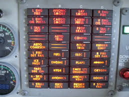
You are working for The Jet Propulsion Laboratory (JPL) Division of NASA testing a new and highly experimental spacecraft capable of in atmosphere flight as well as outer orbit maneuvering. Lieutenant Pete “Maverick” Mitchell has been testing the new spacecraft now for a few weeks, and has had continuous issues with the warning light for power delivery failure to the stabilizers on the wings.

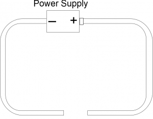
Maverick is convinced that the time between when the problem happens and when the warning light comes on is way too long, and this delay in relaying the warning to him could lead to a very problematic incident in the future. He does not want to loose another Goose. You have been given the task of explaining to Maverick why this could not be the case, and your boss, Clint Howard, has given you the following circuit diagram to try and aid you in your explanation to Maverick. The circuit diagram at this time does not include the warning light.
Maverick likes numbers, so part of your explanation should also include a calculation of the amount of time it takes the light to come on when the length of the wire in the circuit between the stabilizer control module switch and the warning light in the cockpit is 5.2$m$ distance. He should also understand what the electric field looks like in this circuit, and why it means that his original presumptions about the warning light “taking too long” cannot be correct. You should also correct this circuit diagram to include the warning light so that your boss has a more accurate circuit diagram to show people.
