This is an old revision of the document!
Example: Application of Node Rule
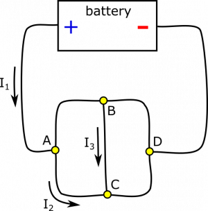
Suppose you have the circuit below. Nodes are labeled for simplicity of discussion. you are given a few values: $I_1=8 \text{ A}$, $I_2=3 \text{ A}$, and $I_3=4 \text{ A}$. Determine all other currents in the circuit, using the Current Node Rule. Draw the direction of the current as well.
Facts
- $I_1=8 \text{ A}$, $I_2=3 \text{ A}$, and $I_3=4 \text{ A}$.
- $I_1$, $I_2$, and $I_3$ are directed as pictured.
Lacking
- All other currents (including their directions).
Approximations & Assumptions
- The current is not changing.
- All current in the circuit arises from other currents in the circuit.
Representations
- We represent the situation with diagram given.
- We represent the Node Rule as $I_{in}=I_{out}$.
Solution
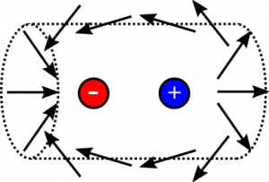
First, notice that we probably do not want to do any calculations here, since the it will not be fun to take a dot-product of the dipole's electric field and the area-vector, and it will get very messy very quickly when we start integrating over the surface of the cylinder. Instead, we evaluate the situation more qualitatively. Consider the electric field vectors of the dipole near the surface of the cylinder:

Notice that the vectors near the positive charge are leaving the cylinder, and the vectors near the negative charge are entering. Not only this, but they are mirror images of each other. Wherever an electric field vector points out of the cylinder on the right side, there is another electric field vector on the left that is pointing into the cylinder at the same angle. These mirror image vectors also have the same magnitude, though it is a little tougher to visualize.
We could write this as a comparison between the left and right side of the cylinder. The $\text{d}\vec{A}$-vectors are mirrored for left vs. right, and the $\vec{E}$-vectors are mirrored, but opposite $\left(\vec{E}_{left}=-\vec{E}_{right}\right)$. We tentatively write the equality, $$\Phi_{left}=-\Phi_{right}$$
Putting it together, we tentatively write: $$\Phi_{\text{cylinder}}=\Phi_{left}+\Phi_{right}=0$$ We gain more confidence when we read the next section of notes, where we define “Gauss' Law”. This law states that the total flux through a close surface is the amount of charge enclosed divided by $\epsilon_0$, the permittivity of free space. $$\Phi_{\text{total}}=\int \vec{E} \cdot \text{d}\vec{A}=\frac{Q_{\text{enclosed}}}{\epsilon_0}$$ Since the total charge of the dipole is $0$, then indeed the charge enclosed is $0$, and we were correct with our reasoning about the electric field and flux above.
