This is an old revision of the document!
Resistance of a Wire
Suppose you have a wire whose resistance you know. The wire has a length of 2 cm, and has a cross-sectional area of 1 mm$^2$. The resistance of the wire is 50 m$\Omega$.
Facts
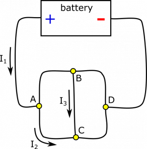
- $I_1=8 \text{ A}$, $I_2=3 \text{ A}$, and $I_3=4 \text{ A}$.
- $I_1$, $I_2$, and $I_3$ are directed as pictured.
Lacking
- All other currents (including their directions).
Approximations & Assumptions
- The current is not changing (circuit is in steady state).
- All current in the circuit arises from other currents in the circuit.
- No resistance in the battery (approximating the battery as a mechanical battery)
Representations
- We represent the situation with diagram given.
- We represent the Node Rule as $I_{in}=I_{out}$.
Solution
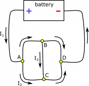
Let's start with node $A$. Incoming current is $I_1$, and outgoing current is $I_2$. How do we decide if $I_{A\rightarrow B}$ is incoming or outgoing? We need to bring it back to the Node Rule: $I_{in}=I_{out}$. Since $I_1=8 \text{ A}$ and $I_2=3 \text{ A}$, we need $I_{A\rightarrow B}$ to be outgoing to balance. To satisfy the Node Rule, we set $$I_{A\rightarrow B} = I_{out}-I_2 = I_{in}-I_2 = I_1-I_2 = 5 \text{ A}$$
We do a similar analysis for node $B$. Incoming current is $I_{A\rightarrow B}$, and outgoing current is $I_3$. Since $I_{A\rightarrow B}=5 \text{ A}$ and $I_3=4 \text{ A}$, we need $I_{B\rightarrow D}$ to be outgoing to balance. To satisfy the Node Rule, we set $$I_{B\rightarrow D} = I_{out}-I_3 = I_{in}-I_3 = I_{A\rightarrow B}-I_3 = 1 \text{ A}$$
For node $C$, incoming current is $I_2$ and $I_3$. There is no outgoing current defined yet! $I_{C\rightarrow D}$ must be outgoing to balance. To satisfy the Node Rule, we set $$I_{C\rightarrow D} = I_{out} = I_{in} = I_2+I_3 = 7 \text{ A}$$
Lastly, we look at node $D$. Incoming current is $I_{B\rightarrow D}$ and $I_{C\rightarrow D}$. Since there is no outgoing current defined yet, $I_{D\rightarrow battery}$ must be outgoing to balance. To satisfy the Node Rule, we set $$I_{D\rightarrow battery} = I_{out} = I_{in} = I_{B\rightarrow D}+I_{B\rightarrow D} = 8 \text{ A}$$
Notice that $I_{D\rightarrow battery}=I_1$. This will always be the case for currents going in and out of the battery (approximating a few things that are usually safe to approximate, such as a steady current). In fact, we could have treated the battery as another node in this example. Notice also that if you incorrectly reason about the direction of a current (incoming or outgoing), the calculation will give a negative number for the current. The Node Rule is self-correcting. A final diagram with directions is shown below.

