Project 7
Project 7A: Artemis's Last Hope
Part 1:
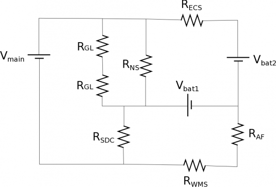
After you stabilized Johnny 5, team leader Melissa Lewis decides Artemis 13 needs to go home before anything else happens. Just as she gives the order to rotate boosters in order to send the ship home, the crew feels the spacecraft rock violently and warning lights start going off everywhere. The command ship starts to lose all of its power (maybe it had something to do with not being able to get the special tape from the STICKYSTUFF corporation at Lakeview). After a quick investigation, it turns out that the circuit that controls all of the key systems is currently drawing too much current from the battery. You are in constant communication with Austin about the issues you are encountering and a bright but intense intern proposes a risky but possibly brilliant solution. They want to take two batteries from the mostly dead Command Ship and use them to help power the Artemis. In addition to the 230 V main battery, they say they need 140 V ($V_{bat1}$) from the Command Ship battery and only 5 V ($V_{bat2}$) from the backup battery to get them home. From the ship manual you find the following resistances for different components that need to be powered in order to get you all home:
- Gauge Lights: $R_{GL}=100\Omega$
- Navigation System: $R_{NS}=700\Omega$
- Steering/Direction Control: $R_{SDC}=950\Omega$
- Engine Cooling System: $R_{ECS}=500\Omega$
- Air Filter: $R_{AF}=300\Omega$
- Waste Management System: $R_{WMS}=425\Omega$
Will this circuit work without drawing any more than the 0.35 A from the main battery?
Part 2:
The other suggestion on the table is rather than putting in two back up batteries, you replace them with capacitors. What would be the effect on the circuit if this were the case? Would it be better to use batteries or capacitors to get the astronauts home?
Project 7B: Austin, we have a snafu
The Artemis 13 is almost home but before they complete their final landing sequence the team need to launch a top-secret deep space probe that will be piloted by Johnny 5 into the eye of the storm over Lakeview. However, power supply for the whole ship is running critically low, so you are now only running the ECS to maintain oxygen in the command module. You have to somehow power up the probe to complete your mission. You no longer have communications with Austin.
You notice as you begin powering up the probe (which operates on its own reserve power system) that although the navigational controls have been primed, there are several components that are not responding to testing. It appears that the circuit switch control board got fried during the test jump, as a result, you now need to create a new circuit that will allow you to provide different amounts of energy to the propulsion system's module on the probe.
That propulsion system consists of the primary burners and the cooling system, which have a total resistance of 65 $\Omega$. The primary burners require a short burst of 200 J to power-up. The cooling system requires a short burst 300 J to power-up.
You need to be able to deliver different amounts of power to this module; however, you are growing concerned that the power supply the probe has access to of 100 V may not be sufficient to power these probe systems. You manage to find some additional batteries onboard (three 10 V batteries from the supply room) to use if you need them.
You also have several 0.125F capacitors and resistors (1 $\Omega$, 5 $\Omega$, 10 $\Omega$, 50 $\Omega$, 100 $\Omega$) on hand. You also have access to multiple switches that can be used to open and close parts of the circuit you are designing.
There is a breaker in the circuit that is a failsafe and will trip if the current reaches 2 A. You also know that there are delicate circuit elements in the primary burners and the cooling system, so the propulsion system should not be connected to any power supplies when charging capacitors.
You should provide a circuit diagram of your design that helps you explain to your crew that the current in the circuit is safe and that you are going to be able to supply the needed power to the systems when the time comes to launch the probe. As a check for yourself, you should make sure that the voltage in the circuit adds up to the correct amount as to not suffer any voltage shortages.
Learning Goals
- Understand how capacitors charge and discharge
- Use the relationship between capacitance and energy
- Understand what happens when capacitors are in parallel or in series
- Understand how capacitors and resistors combine in a complex circuit
